2007 Nissan Altima L32 Fuse Box Diagram
The 2007 Nissan Altima (L32) has 3 fuse boxes. Choose the one you’re looking at.
Find a fuse
Search by component, fuse number or description.
Popular searches
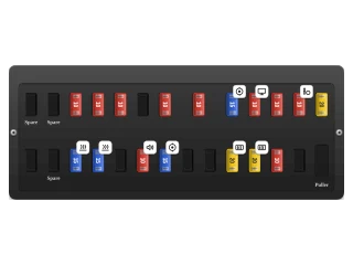
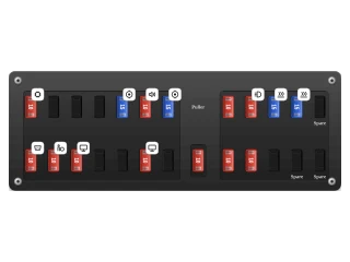
Passenger compartment fuse block
In the first L32 Altima the passenger fuse block sits low on the driver's side, under the instrument panel and to the left of the steering column, behind a pull-off cover. Nissan's October 2006 service manual, the first written for this sedan, draws it; the 2007 owner's manual only shows where it is and says the ratings are on the cover.
Mini fuses stand on end in two rows. The top row counts 1 to 5 from the right, then 6 alone in a gap, then 7 to 11 and two spare pockets at the left end. The lower row starts with 12 under fuse 2 and runs left to 22, ending in one spare; the fuse puller clips in under fuse 1. On this first edition the console socket (5) and the front socket (18) are 15 A, and cell 8 carries a 15 A rating with no circuit behind it.
| No. | Function | Amp | Description |
|---|---|---|---|
| 1 | 20 AMINI | HEATED SEATS (IGN): front seat heaters, on cars that have them | |
| 2 | 10 AMINI | AIRBAG (IGN): SRS air bag diagnosis sensor unit | |
| 3 | 10 AMINI | ELEC PARTS (IGN): air conditioner control, body control module, audio, compass, CVT and engine control, inside mirror, rear defogger relay, tyre pressure monitor | |
| 4 | 10 AMINI | METER (IGN): combination meter, back-up lamps, ABS/VDC, charging warning, CVT, air bag lamp, turn signals and warning chime | |
| 5 | 15 AMINI | RR POWER SOCKET (BAT): console power socket (15 A in the 2007-2009 books, 20 A from the 2010 book) | |
| 6 | 10 AMINI | ELEC PARTS (BAT): battery feed to the body control module, Intelligent Key, air conditioner, CVT and engine control, HomeLink; the fuse to pull for long-term storage | |
| 7 | 10 AMINI | STOP LAMP (BAT): stop lamp switch, ABS/VDC, CVT and engine control, body control module, Intelligent Key | |
| 8 | 15 AMINI | Rated 15 A on the October 2006 plate, but no circuit in the 2007 wiring diagrams; the July 2007 and later books leave it empty | |
| 9 | 10 AMINI | PUSH ENG START (BAT): Intelligent Key push-button start, interior room lamp timer, NVIS immobiliser, warning chime | |
| 10 | 10 AMINI | ROOM LAMP (BAT): body control module battery feed for lamps, wipers, door locks, power windows, sunroof and security system | |
| 11 | 10 AMINI | METER (BAT): combination meter, headlamp and turn signal logic, Intelligent Key, tyre pressure monitor, CVT, security system | |
| 12 | Not used | ||
| 13 | 10 AMINI | HEATED MIRROR (IGN): heated door mirrors, switched by the rear window defogger relay | |
| 14 | 20 AMINI | RR DEF (IGN): rear window defogger, first supply | |
| 15 | 20 AMINI | RR DEF (IGN): rear window defogger, second supply | |
| 16 | Not used | ||
| 17 | Not used | ||
| 18 | 15 AMINI | FR POWER SOCKET (ACC): front power socket and cigarette lighter (15 A in the 2007-2009 books, 20 A from the 2010 book) | |
| 19 | 10 AMINI | AUDIO/MIRROR (ACC): audio unit, navigation and AV control, door mirror remote control, body control module | |
| 20 | Not used | ||
| 21 | 15 AMINI | BLOWER MOTOR (IGN): heater and air conditioner blower, first supply | |
| 22 | 15 AMINI | BLOWER MOTOR (IGN): heater and air conditioner blower, second supply |
Engine compartment IPDM E/R
The intelligent power distribution module (IPDM E/R) is the large white unit at the front of the engine bay on the driver's side, beside the battery, under a clip-on lid. The 2007 books print no rated table for it: the October 2006 service manual draws the module's fuse banks in its terminal layout, and its wiring diagrams give every rating.
Mini fuses lie flat in four banks around the two big harness connectors. Down the upper left are 32 to 38, fuel pump to washer; the lower left holds 40 to 43, including the 10 A steering column lock relay fitted to 2007 cars. The right side carries 46 to 49 for the parking, tail and high-beam lamps, and below them 51 to 55 for the low beams, fog lamps, Canadian daytime lights and the 30 A wiper fuse. Numbers 39, 44, 45 and 50 have no fuse.
| No. | Function | Amp | Description |
|---|---|---|---|
| 32 | 15 AMINI | FUEL PUMP: fuel pump relay and fuel pump | |
| 33 | 10 AMINI | Ignition relay-1 circuit: starter control, park/neutral position switch, cooling fan relay-3 | |
| 34 | 10 AMINI | A/T CONT: CVT (transmission) control module and its speed sensors | |
| 35 | 10 AMINI | INJECTOR: fuel injectors and the engine control module | |
| 36 | 10 AMINI | ABS CONT: ABS/VDC actuator and electric unit | |
| 37 | 15 AMINI | O2 SENS: air/fuel ratio sensor 1 and heated oxygen sensor 2 | |
| 38 | 10 AMINI | WASHER MTR: windscreen washer pump | |
| 40 | 10 AMINI | STEERING LOCK: electronic steering column lock relay (Intelligent Key cars) | |
| 41 | 10 AMINI | AIR COND: air conditioner relay and compressor clutch | |
| 42 | 15 AMINI | ENG CONT: ECM relay - ignition coils, condensers, EVAP and intake valve timing solenoids, mass air flow sensor | |
| 43 | 15 AMINI | THROTTLE MTR: electric throttle control motor relay | |
| 46 | 10 AMINI | CLEARANCE LAMP: front parking lamps | |
| 47 | 10 AMINI | TAIL LAMP: tail lamp relay - tail, licence plate and illumination lamps via the fuse block | |
| 48 | 10 AMINI | H/LAMP HI LH: left headlamp high beam | |
| 49 | 10 AMINI | H/LAMP HI RH: right headlamp high beam | |
| 51 | 15 AMINI | H/LAMP LO LH: left headlamp low beam | |
| 52 | 15 AMINI | H/LAMP LO RH: right headlamp low beam | |
| 53 | 15 AMINI | FR FOG LAMP: front fog lamp relay and fog lamps | |
| 54 | 10 AMINI | DTRL: daytime running light system (Canadian cars) | |
| 55 | 30 AMINI | FR WIPER: front wiper relay and wiper motor |
Engine compartment fuse and fusible link box
This narrow black box carries the car's large fusible links and eight more blade fuses. It is in the engine compartment next to the IPDM E/R, and the October 2006 plate for it draws the cooling fan relay-3 and the horn relay only as dashed outlines.
With the plate's front arrow pointing right, the top row holds the links F, G, H and I and then fuses 24 to 27; the lower row holds fuses 28 to 31 and then links J to M. Nissan letters the links, so each is drawn as a socket with its letter and rating underneath. This first edition crosses out both I and J while its own wiring diagram feeds the body control module from a 40 A link it calls J; every later book prints that link at I, so it is shown there.
| No. | Function | Amp | Description |
|---|---|---|---|
| 24 | 15 AMINI | AUDIO: audio unit on base systems, Bose amplifier on Bose cars | |
| 25 | 15 AMINI | AUDIO AMP: Bose amplifier, first supply (cars with the Bose system) | |
| 26 | 15 AMINI | AUDIO AMP: Bose amplifier, second supply (cars with the Bose system) | |
| 27 | Not used | ||
| 28 | Not used | ||
| 29 | 10 AMINI | ALTNTR: alternator (charging system) | |
| 30 | 15 AMINI | HORN: horn relay, Intelligent Key and vehicle security horn | |
| 31 | 10 AMINI | Intelligent Key engine start, starting system, NVIS immobiliser, body control module |
Other Nissan Altima model years
 2012 Nissan Altima L32
 2011 Nissan Altima L32
 2010 Nissan Altima L32
 2009 Nissan Altima L32
 2008 Nissan Altima L32
 2018 Nissan Altima L33
 2017 Nissan Altima L33
 2016 Nissan Altima L33
 2015 Nissan Altima L33
 2014 Nissan Altima L33
 2013 Nissan Altima L33
 2006 Nissan Altima L31
 2005 Nissan Altima L31
 2004 Nissan Altima L31
 2003 Nissan Altima L31
 2002 Nissan Altima L31